
A verified view methodology is a documented, survey-anchored process that ties a photographic baseline to a matched virtual camera, so a rendered proposal can be independently checked by planning officers. For UK planning submissions, the essential requirement is simple: the camera position must trace back to Ordnance Survey coordinates, and the whole process must sit inside a written Technical Methodology that a planner, or their consultant, could follow step by step.
TL;DR:
- Survey control must include multiple points, including the camera position, and be referenced to the OSGB36 grid with documented OSTN15 transformation to ensure accurate verification.
- Photographs should be single-frame, 24mm equivalent lenses taken from a fixed, leveled tripod position with intact EXIF data, avoiding stitching to maintain a clear evidential chain.
- The verified camera alignment relies on matching surveyed ground points to positioning in the 3D model, using objective overlay checks rather than visual approximation.
- Rendering lighting must match the photograph’s sun position based on EXIF data, with masking for occlusions and materials that avoid overstating finish or reflectivity.
- The complete verified view package should include raw files, survey spreadsheets, 3D models, layered compositing files, a technical methodology report, annotated AVR sheets, and a clear statement of verification level.
Table of Contents
- What is a verified view methodology in planning terms?
- What is the correct photographic procedure for a verified baseline?
- How do you record survey control for a verified view?
- How do you verify the virtual camera against the photograph?
- How do you match render lighting and composite the final image?
- What should the graticule and sheet presentation include?
- How do you choose the right level of verification?
- What should a planning-ready verified view package contain?
- How does this methodology work in practice on a live project?
- Where is verified view practice heading next?
- How Visual Trick delivers verified views for planning submissions
- Sources
- FAQ
What is a verified view methodology in planning terms?
A verified view methodology is the paper trail behind a photomontage. It is not the picture itself. It is the survey data, camera settings, and modelling decisions that let a third party check whether the rendered building really would appear where the artist has drawn it.
Local planning authorities have grown wary of “pretty” visuals that cannot be checked. A striking render with no supporting data is, in evidential terms, worth roughly the same as an artist’s impression sketched on a napkin. Planning committees know this, and increasingly ask for proof rather than polish. That shift explains why guidance from the Landscape Institute technical guidance note: visual representation (TGN 06/19) and the London View Management Framework (LVMF) both push toward documented, reproducible workflows rather than one-off artistic renders.
The workflow breaks into seven linked stages, and missing anyone of them weakens the whole chain of evidence:
- Scoping: agree the viewpoint, the verification level, and what the local authority actually expects before anyone picks up a camera.
- Photo baseline: capture a single, undistorted reference photograph from a documented, re-locatable position.
- Survey control: record coordinates for the camera and multiple reference points, tied to the Ordnance Survey national grid.
- Model alignment: place the 3D model and virtual camera using those same coordinates, then verify the match against the photograph.
- Render and lighting: reproduce sun position and time of day so the rendered light matches the photograph’s light.
- Composite: layer the render into the photograph, masking correctly for anything the proposal would hide or reveal.
- Documentation: write the Technical Methodology statement that explains every decision above.
Each stage generates its own audit trail. A surveyor’s spreadsheet of eastings, northings, and levels. A photographer’s field notes on tripod height and lens choice. A visualiser’s render log showing sun angle and camera field of view. Stitch these together and you get something planners can interrogate, rather than simply admire.
“Verification” itself means three things in this context. First, traceability: every number in the final image can be traced to a source, whether that is a survey point or an EXIF timestamp. Second, reproducibility: another competent professional, given the same data, could recreate the same camera position and broadly the same result. Third, auditability: the deliverable package includes enough raw material (spreadsheets, marked-up images, methodology notes) that a planning officer’s own consultant could check the claims without needing to trust the applicant’s word.
Guidance on what counts as “enough” verification is not spread evenly across the UK. The Landscape Institute’s TGN 06/19 sets a general, proportionality-led framework for any landscape or townscape visualisation, applicable to new commissions from 17 September 2019 onward. The LVMF, meanwhile, is written specifically for London’s ten protected panoramas and their associated Assessment Points, and its Appendix C on Accurate Visual Representations is often treated as the practical gold standard even outside the capital, because it is the most detailed public document on camera setup, field of view, and annotation. Many individual local planning authorities then publish their own appendices, often within Environmental Statement templates, translating that national guidance into local expectations, for example around lens choice or coordinate referencing.
Reading all three together matters more than reading any one in isolation. A townscape consultant working on a scheme near a London Assessment Point needs LVMF’s specific rules. An architect submitting a scheme in a market town needs the Landscape Institute’s proportionality principle and whatever local appendix their planning authority has published. Where the two overlap, and they usually do on core technical points like camera height or survey control, following the stricter of the two rarely causes a problem. Ignoring both usually does.
What is the correct photographic procedure for a verified baseline?
The baseline photograph is the fixed point everything else in the methodology gets checked against, so any error here propagates through the entire submission. Get the camera position wrong, or fail to document it properly, and no amount of clever modelling downstream will rescue the verification.
Follow this sequence on site:
- Mark and photograph the tripod position. Before levelling the camera, take a plumb-line photograph looking straight down at the tripod’s ground mark, and record that mark’s location relative to a permanent feature (a manhole cover, a kerb corner, a fence post) so a surveyor can return to exactly the same spot later.
- Set the camera to the standard height. Local authority appendices typically specify a camera height of 1.60 metres, chosen as a reasonable approximation of average eye level. Depart from this only with good reason, and document why if you do.
- Level the horizon precisely. A tilted or converging horizon introduces three-point perspective, which distorts verticals and makes later overlay comparison unreliable. Use a spirit level or the camera’s built-in level, and check the horizon line runs true across the whole frame.
- Choose a fixed, moderate-wide lens rather than stitching. A 24mm equivalent lens, giving a horizontal field of view of roughly 68 degrees, is the typical starting point cited in local authority procedures, striking a balance between capturing enough context and avoiding the barrel distortion that wider lenses introduce at the frame edges.
- Capture EXIF data and avoid heavy processing. Leave the camera’s date, time, and GPS metadata intact, and resist the temptation to crop, straighten, or colour-correct the baseline file. Any processing should happen on a working copy, with the original preserved untouched as the evidential record.
Local authority appendices are explicit about avoiding stitched panoramas for verified work, because stitching software blends multiple exposures with slightly different optical centres, producing seams and perspective inconsistencies that are almost impossible to reproduce exactly when someone else tries to verify the image later, as local authority guidance on verified view methodology sets out. A single frame from a fixed position, even if it shows a slightly narrower view than a stitched composite, gives a cleaner evidential chain. Studio practice elsewhere in the sector echoes this preference, generally favouring single-frame 24mm captures with shift-capable lenses specifically to avoid the distortion that would otherwise creep in at wider apertures, as one studio’s verified views methodology overview describes.
Pro Tip: Photograph a printed sheet showing the date, time, and site reference held next to the tripod before you take the main shot. It costs thirty seconds on site and saves an argument months later when a planning officer questions whether the image was really taken when you say it was.

How do you record survey control for a verified view?
Survey control is what turns “we think the camera was about here” into a coordinate a planner can check on a map. Every verified view methodology worth the name rests on this data, and it needs to be handed over as raw numbers, not folded invisibly into a rendered image.
Get the referencing right from the outset. Coordinates should sit on the OSGB36 national grid, with the transformation to that grid documented using Ordnance Survey’s OSTN15 transformation, the current standard method for converting GPS-derived positions into the OSGB36 system with the accuracy planning verification demands. Elevation figures should be tied to Ordnance Survey Datum (OSD), not an arbitrary site benchmark, so height differences between the camera and the proposed structure mean the same thing to everyone reading the drawings.
A single control point is not enough. The survey needs multiple stations, deliberately including one at the camera position itself, plus a spread of reference points across the depth and height of the photographed scene:
- Camera station coordinates: easting, northing, and level for the exact tripod position, tied to a permanent ground mark.
- Foreground and midground points: identifiable features (kerb lines, lamp posts, building corners) at varying distances from the camera, giving the verification routine enough spread to confirm scale and depth.
- Background or elevated points: rooflines, chimney stacks, or distant landmarks that help pin down camera tilt and vertical field of view.
- A marked-up reference image: the baseline photograph annotated to show exactly which pixel corresponds to which surveyed point.
The deliverable that ties all this together is deceptively simple: a spreadsheet listing point ID, easting, northing, level, and a short description of what the point actually is on the ground. This is the single most useful document in the whole package for a reviewing consultant, because it lets them check the geometry independently of the rendered image entirely. Local authority appendices consistently ask for this exact format, tied to OSGB36 with an OSTN15 statement confirming how the transformation was applied, as the local authority verified view methodology appendix sets out.
One detail trips up more submissions than it should: mixing coordinate systems. A survey done in a local site grid, or referenced to WGS84 without a documented conversion, cannot be meaningfully compared to a planning authority’s own GIS layers. State the coordinate reference system explicitly on every drawing and in every spreadsheet, even when it feels repetitive. It is the detail that saves a resubmission.
How do you verify the virtual camera against the photograph?
Getting the model and the virtual camera correctly aligned is where the survey data actually earns its keep. This is the stage that proves, rather than merely asserts, that the rendered building would occupy a specific position in the real view.
Start by importing the 3D model with its origin tied to real OS coordinates, not an arbitrary local origin the design team happened to use during earlier design development. Every element in the scene, existing buildings, ground topography, the proposed structure, needs to sit on the same coordinate system the survey used. Then set the virtual camera’s position, height, and orientation directly from the surveyed camera station data, rather than eyeballing it against the photograph.
The verification step itself follows a clear logic:
- Identify matching points. Select several surveyed points visible in the photograph (the same foreground, midground, and background points recorded during the survey) and locate their equivalents in the 3D scene.
- Run the overlay check. Render a wireframe or simple geometry pass from the virtual camera and overlay it against the photograph. Matching points should align within an acceptable tolerance, not drift progressively toward the frame edges.
- Use intersection routines where available. Rather than relying on visual judgement alone, many modelling packages can calculate the single camera position where all surveyed points simultaneously align with their photographed locations, which is a more objective test than eyeballing an overlay.
- Check field of view against the photograph’s lens. A mismatch here shows up as points that align at the centre of the frame but diverge toward the edges, the classic sign of a virtual camera using the wrong focal length.
- Document any assumptions. If a survey point was unavailable and a feature was positioned by estimation instead, say so plainly in the methodology, rather than letting it pass as if it were surveyed.
This point-matching and intersection approach produces genuinely objective positional verification, in contrast to a visualiser simply nudging a camera until the render “looks about right” against a reference photograph. The distinction matters to a reviewing officer, because the first can be independently repeated by someone else and the second cannot.
Modelling limits deserve honesty too. If the proposed building’s exact cladding profile is not yet finalised, or a landscaping scheme is indicative rather than detailed, the Technical Methodology should state that plainly rather than let the render’s apparent precision imply a level of design certainty that does not exist yet.
How do you match render lighting and composite the final image?
Lighting is the detail that gives a technically correct verified view away as fake or convincing, often before a viewer consciously registers why. Get the sun in the wrong place and even perfectly aligned geometry looks off.
The fix is straightforward in principle. Pull the exact date and time from the baseline photograph’s EXIF metadata, combine it with the site’s latitude and longitude, and calculate the sun’s real position at that moment. Most rendering packages accept these inputs directly and will place a virtual sun that casts shadows matching the photograph’s shadows in length and direction.
- Match shadow direction and length, not just general “sunny day” brightness, since mismatched shadows are the fastest way a reviewer spots a poorly matched render.
- Mask the proposal correctly behind existing fabric, so trees, neighbouring buildings, or street furniture that would genuinely occlude the new structure are shown occluding it, and record each masking decision in the methodology.
- Work with the architect on likely materials rather than guessing, since render realism depends heavily on getting cladding, glazing, and roofing materials right.
- Avoid overstating reflectivity or texture. A speculative render of glass or polished stone can look more finished, and more convincing, than the design detail actually justifies at this stage.
- Run a final compositing check comparing the composite against the original baseline pixel-for-pixel outside the masked area, confirming nothing beyond the proposal itself has shifted.
Pro Tip: If material specifications are not locked in when the render is due, use a deliberately neutral, matte material rather than a specific finish. It keeps the image honest and avoids having to explain later why the render showed a stone finish that got value-engineered into render board.
What should the graticule and sheet presentation include?
The graticule is the on-image annotation that turns a rendered picture into an evidential document. Without it, a planning officer has no quick way to check field of view, time of capture, or scale, and has to dig through a separate methodology document for every basic fact.
Include these elements directly on the image or its immediate border:
- Date and time of capture, taken from the photograph’s EXIF data, printed clearly enough to read at A3 scale.
- Horizon markers, showing the true horizontal line across the frame so a reviewer can spot any residual tilt.
- Field of view markers with degree labelling, typically shown as vertical tick marks at set degree intervals across the frame width.
- A locational accuracy statement, giving the coordinate reference and stating the declared verification level (in practice, most local authorities and the LVMF distinguish something like a Type 1 sketch view through to a Type 4 fully verified photomontage).
For a fully verified Type 4 submission, present the material as three coordinated sheets rather than a single composite image: the annotated baseline photograph with its methodology summary, a wireframe or wireline overlay showing the geometry check, and the final photomontage, all printed at identical scale so a reviewer can flip between sheets and compare like for like. Planning guidance built on Landscape Institute principles specifically recommends this coordinated three-sheet format, precisely because a single flattened image hides the verification steps that a reviewer actually needs to see, as guidance referencing LI TGN 06/19 sets out.
How do you choose the right level of verification?
Not every viewpoint on a scheme needs the full Type 4 treatment, and the Landscape Institute is explicit on this point: choose the minimum level of verification that is still fit for purpose, then document why that level was chosen. Over-specifying verification wastes budget and design time; under-specifying it invites a planning refusal or a request for further information that delays the whole application.
A few practical triggers tend to push a project toward the higher end of the scale:
- Designated views and Protected Vistas. Any scheme visible from one of London’s LVMF Assessment Points, or from an equivalent locally designated view, should generally assume Type 4 verification is expected, since the LVMF’s assessment process is built around exactly this level of scrutiny.
- Height or massing that changes a skyline. Tall buildings, or anything that would sit above an existing roofline in a sensitive setting, invite closer scrutiny than a single-storey extension.
- Heritage settings and protected sites. Where a proposal sits near a listed building, conservation area, or other protected asset, checking the site’s status early, using resources like Gov, helps establish whether additional consultation bodies need to see the verified views before submission.
- Local authority track record. Some planning authorities are simply stricter than others on visualisation standards; a quick look at recently approved schemes of similar scale in the same authority area is a fast way to gauge expectations.
Whatever level is chosen, record the reasoning in the Technical Methodology statement itself, not just in an internal project file. A one-paragraph justification, referencing the relevant guidance and the scheme’s sensitivity, closes off the most common reason officers request further verification: they simply cannot see why a lower level was considered adequate. Agreeing this scope with the local planning authority before commissioning the visualisation work, rather than after a first submission gets queried, is the single most effective way to avoid rework.
What should a planning-ready verified view package contain?
A complete submission package needs specific files and statements, not just a finished-looking image. Missing any item below is the most common reason a planning officer sends a verified view back for clarification.
- Photographic originals with intact EXIF data, plus the plumb-line tripod location photograph and any marked-up reference images showing surveyed points.
- The survey spreadsheet: point ID, easting, northing, level, description, plus a written statement confirming the coordinate reference system and the OSTN15 transformation applied.
- The 3D model file (or export) tied to OS coordinates, together with a record of the virtual camera’s exact position, height, orientation, and field of view settings.
- Render files and layered composite files, kept separate rather than flattened, so a reviewer’s own consultant could re-open the masking and lighting layers if challenged.
- The Technical Methodology document, covering every decision above in plain language.
- Graticule-framed AVR sheets, presented at the agreed verification level and printed scale.
- A short statement of accuracy and proportionality, explaining the declared verification level and why it fits the scheme.
| Deliverable | Format | Who typically produces it |
|---|---|---|
| Baseline photograph and tripod location image | RAW/JPEG with EXIF intact | Photographer or visualisation studio |
| Survey point spreadsheet | Spreadsheet, OSGB36 coordinates | Chartered surveyor |
| Virtual camera and model file | 3D model export | Visualisation studio |
| Technical Methodology statement | Written document | Visualisation studio or applicant’s consultant |
| Graticule-framed AVR sheets | Print-ready PDF at declared scale | Visualisation studio |
Keep this checklist next to the brief when commissioning the work, and use it again before submission as a final quality check against the finished package. Visual Trick’s own property architect visualisation checklist walks through a comparable list from the architect’s side of the brief, which is worth cross-referencing if you are assembling the deliverables in-house rather than commissioning them.
How does this methodology work in practice on a live project?
The stages above are not theoretical. Visual Trick applies this exact sequence on planning commissions: a brief that fixes the viewpoint and verification level, survey coordination to get camera and reference points onto the OS grid, a documented photography visit, model alignment and verification against the surveyed points, lighting-matched rendering, and a written Technical Methodology delivered alongside the finished Verified Views.

Because all of this is handled within the same team, there is one point of contact for the survey data, the photography, and the final render. That matters more than it sounds, because a verified view methodology depends on every stage’s data being consistent with the last. A handoff between separate photography, survey, and CGI suppliers is exactly where inconsistencies creep in, whether that is a coordinate system that changes hands without a clear transformation note, or a lens choice that does not match the field of view stated in the methodology.
The practical payoff shows up at the review stage. A planning officer working through a well-documented package, with a spreadsheet of surveyed points and a clear methodology statement, has fewer reasons to send back a request for further information than one working from a render with no supporting data. Fewer queries generally means a faster route through committee.
Where is verified view practice heading next?
Rendering technology keeps getting more photorealistic, and that is precisely why documented process matters more each year, not less. A hyperreal render with no survey data behind it is, if anything, more persuasive and more dangerous than a rough one, because it invites a planning committee to trust an image that nobody has actually checked.
The Landscape Institute’s proportionality principle will likely age well as software makes convincing images easier to produce cheaply. The temptation with better tools is always to make things look more finished than the underlying design actually is, and a documented methodology is the discipline that keeps that temptation in check. My view is that the practitioners who protect their credibility over the next few years will be the ones who stay conservative about material and lighting claims, keep every survey and camera decision traceable, and treat the Technical Methodology statement as seriously as the image itself.
The other shift worth watching is procedural, not technical: early conversations with planning authorities about which verification level actually applies to a scheme. Committing the paperwork before agreeing the scope wastes far more time than the conversation itself ever costs.
— Paride
How Visual Trick delivers verified views for planning submissions
Verified views are handled following this methodology: survey-anchored, documented, and built for scrutiny rather than just presentation. For architects and planning consultants who would rather commission this work than coordinate photographers, surveyors, and modellers separately, using a single provider can help remove the handoff points where data usually goes wrong.
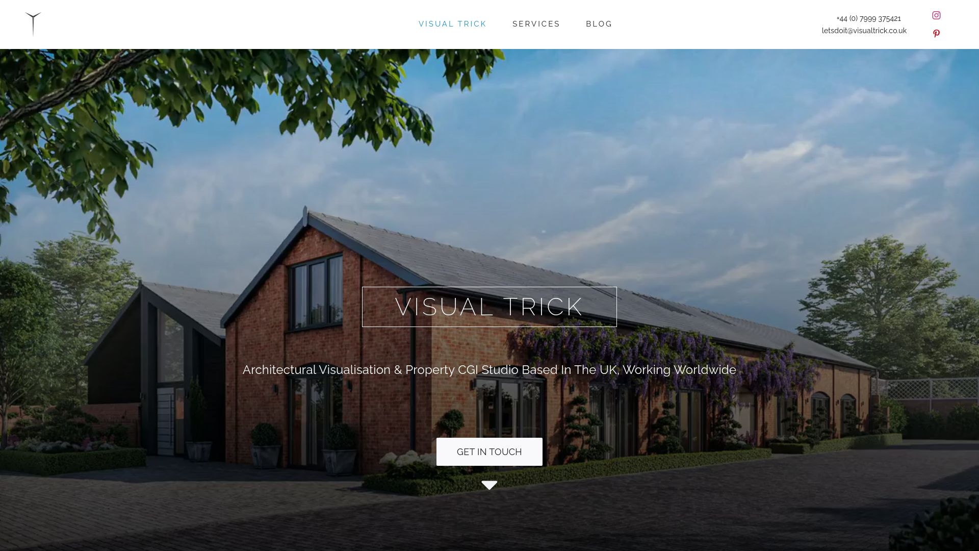
Every commission for CGI Photomontage or Verified Views starts with the same scoping conversation covered above: which viewpoint, which verification level, and what the local planning authority has already indicated it expects. From there, the deliverables follow the checklist in this article, survey coordination, aligned photography, verified camera modelling, lighting-matched rendering, and a written Technical Methodology, so what lands in the planning portal is ready for an officer to check rather than simply admire. If you are scoping a submission and want a clear sense of timelines and deliverables before committing a budget, get in touch through the planning visuals page and ask for a checklist tailored to your viewpoint.
Sources
- Landscape Institute technical guidance note: visual representation (TGN 06/19)
- London View Management Framework (LVMF)
- Appendix: Verified view methodology (local authority planning ES appendix)
- Local planning guidance citing LI TGN 06/19 and verified photomontage appendices
FAQ
What lens should I use for a verified view photograph?
Local authority guidance generally points to a fixed 24mm equivalent lens, giving a horizontal field of view around 68 degrees, as covered in the photographic procedure guidance. Avoid stitched panoramas, since stitching introduces perspective inconsistencies that are difficult to reproduce exactly during verification.
What survey data do I need to supply for a verified view?
You need a spreadsheet of surveyed points with unique IDs, eastings, northings, and levels, referenced to the OSGB36 grid with an OSTN15 transformation statement. Include a station at the camera position itself, plus reference points spread across the foreground, midground, and background of the photographed scene.
How do I justify the verification level I have chosen?
Write a short statement in the Technical Methodology explaining why the chosen level (from a basic sketch through to a fully verified Type 4 photomontage) fits the scheme’s sensitivity, following the Landscape Institute’s proportionality principle. Agreeing the scope with the local planning authority before commissioning the work is the most reliable way to avoid a request for further information later.
Can Visual Trick provide the Technical Methodology document as part of a commission?
Yes. Visual Trick delivers the Technical Methodology statement alongside the Verified Views themselves, covering survey referencing, camera verification, and rendering decisions in one written document. Pricing for this work is available on request through the studio’s planning visuals page.
Do all planning applications need Type 4 verified views?
No. Most schemes need a lower level of verification, and the Landscape Institute explicitly recommends using the minimum level that remains fit for purpose. Type 4, the fully verified photomontage with coordinated baseline, wireline, and photomontage sheets, tends to be reserved for designated views, tall buildings, or heritage-sensitive sites.
